This is one of the most important chapters for a motor seller, because roughly half of all replacement-quotation mistakes are mechanical, not electrical. A motor can have the correct power, voltage, frequency, and speed and still be impossible to install if the mounting or frame size is wrong.
ANALOGY Mounting is like the bolt pattern of a car engine. The engine might make exactly the right power, but if its mounting points don't line up with the chassis, it will never go in the car. A motor is identical: the bolt holes, shaft height, and flange must match the machine, or the perfect electrical spec is worthless. |
4.1 What mounting means
Mounting describes how the motor is mechanically attached to the driven machine — on its feet, by a flange, or both, horizontal or vertical. Most IEC motors follow the mounting designations of IEC 60034-7, which uses two notations that mean the same thing: the older code (B3, B5, B35…) and the newer IM code (IM1001, IM3001, IM2001…). Customers use either freely, so “Mounting: B3” and “Mounting: IM1001” are identical.
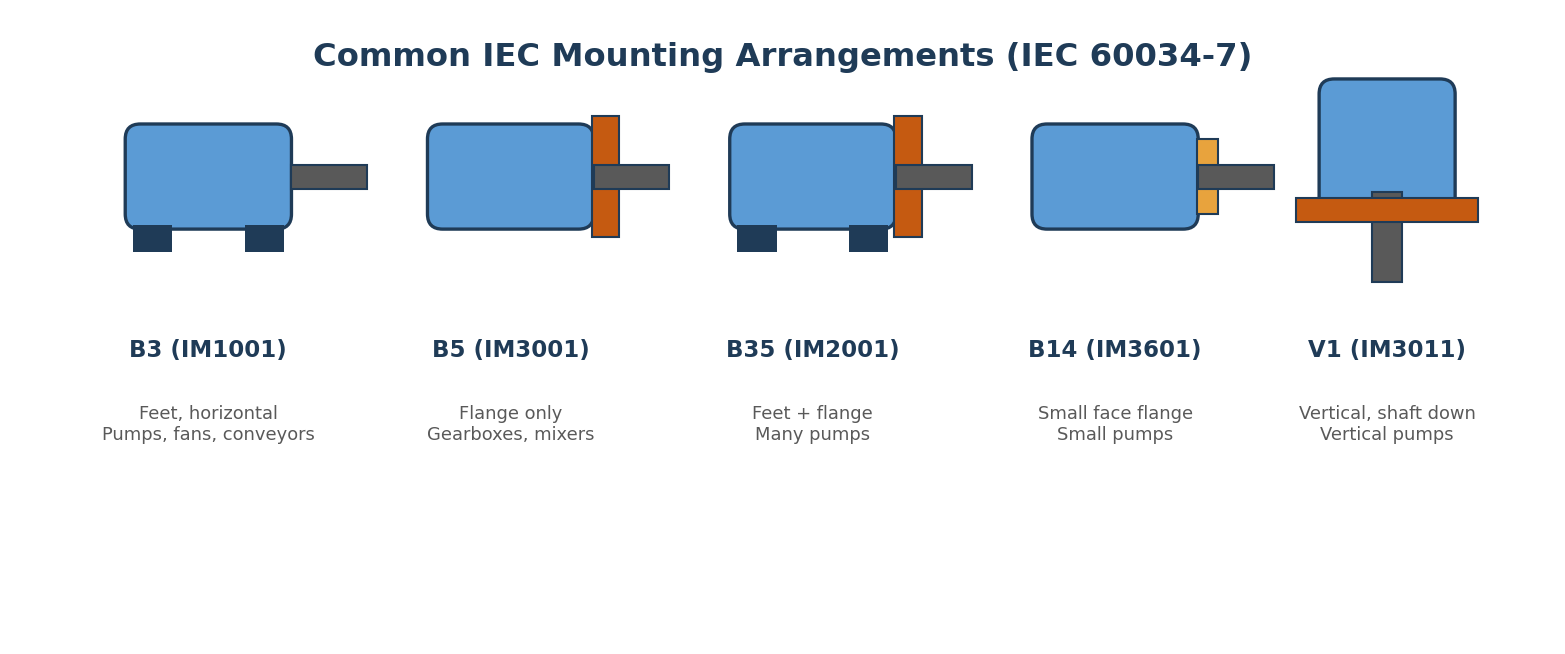
Figure 4.1 — Common IEC mounting arrangements (IEC 60034-7).
4.2 The common arrangements
Code (old / IM) |
Arrangement |
Typical use |
B3 / IM1001 |
Feet, horizontal shaft, bolts to a baseplate |
Pumps, fans, conveyors, compressors — the default 'standard motor' |
B5 / IM3001 |
Large flange, no feet, bolts straight to the equipment |
Gearboxes, pumps, mixers, machine tools |
B35 / IM2001 |
Both feet and flange |
Many industrial pumps — better alignment and support |
B14 / IM3601 |
Smaller face flange |
Small pumps, food and packaging machinery |
V1 / IM3011 |
Vertical, shaft pointing down |
Vertical pumps (often special bearing arrangement) |
WATCH OUT Two classic errors: confusing B5 (flange only) with B35 (feet + flange), and replacing a vertical V1 motor with a horizontal B3. Never substitute one mounting for another without explicit confirmation — the motor will not bolt up. |
4.3 Frame size — the mechanical identity
Frame size defines the motor's physical dimensions. The IEC frame number encodes the shaft height and body length, and from it you can infer shaft height, shaft diameter, foot-hole spacing, body size, and flange dimensions where applicable.
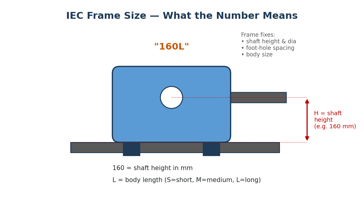
Figure 4.2 — Decoding an IEC frame number such as 160L.
Reading “160L”: the 160 is the shaft centre height in millimetres, measured from the bottom of the feet to the centre of the shaft; the L indicates body length — S (short), M (medium), or L (long). A longer body often allows more copper, higher power, and better cooling at the same shaft height. The frame dimension system is standardised — IEC frame-to-output assignments and dimensions are set out in IEC 60072.
WATCH OUT Same kW does not always mean same frame. Efficiency class, brand, speed, and standard can all shift the frame size. For a replacement, the frame is one of the most important things to match. |
STANDARDS REFERENCE North America uses NEMA frame designations (for example 256T, 326TS, 364T, 365T) defined in NEMA MG-1. IEC and NEMA frames are NOT interchangeable — never offer an IEC frame against a NEMA frame request without checking the actual mounting dimensions. |
4.4 Shaft, flange, and foot dimensions
On a replacement, verify the shaft (diameter, length/extension, keyway width and depth, threaded centre hole, drive end). For a B5/B35 flange, the flange diameter, bolt circle, number and size of bolt holes, and the spigot/register diameter must all match. For a B3 foot motor, check the distance between feet, the bolt-hole spacing, and the shaft height — even two 15 kW motors can differ here if their frames differ.
4.5 Drive end, terminal box position, and rotation
The drive end (DE) is where power leaves the motor — coupling, pulley, gearbox, pump. The non-drive end (NDE) carries the cooling fan, fan cover, and second bearing. Terminal box position is often specified relative to the drive end (“T-box RHS viewed from DE” = right-hand side looking from the shaft). Rotation is given as CW or CCW, normally viewed from the drive end — always confirm the reference side.
4.6 The professional replacement checklist
When a customer asks for an equivalent or replacement motor, never rely on power alone. Gather both the electrical and the mechanical picture:
Electrical |
Mechanical |
Power (kW / HP) |
Frame size |
Voltage |
Mounting (B3 / B5 / B35 / V1 …) |
Frequency |
Shaft diameter and length |
Speed / poles |
Keyway dimensions |
Current (if available) |
Flange dimensions (if flanged) |
Starting method |
Foot dimensions / terminal box position / rotation |
SALES TIP Ideal replacement evidence: a clear nameplate photo, the datasheet, the GA (General Arrangement) drawing, shaft dimensions, mounting, frame, terminal-box location, and the application. With those, you can quote with confidence instead of guessing. |
|
WORKED EXAMPLE RFQ: “30 kW, 400 V, 50 Hz, 4-pole, Frame 200L, B35, IP55, TEFC.” You instantly read: an IEC motor, foot + flange mounted, around 1470 rpm, standard industrial enclosure, continuous duty unless stated otherwise. The mounting (B35) and frame (200L) are as important as the 30 kW. |
Knowledge Check — Chapter 4
What does the mounting code B3 (IM1001) describe?
What is the difference between B5 and B35?
In the frame size 160L, what do '160' and 'L' mean?
Are IEC and NEMA frames interchangeable?
Where is the terminal box if the RFQ says 'T-box LHS viewed from DE'?
List four mechanical items you must verify before offering a replacement motor.